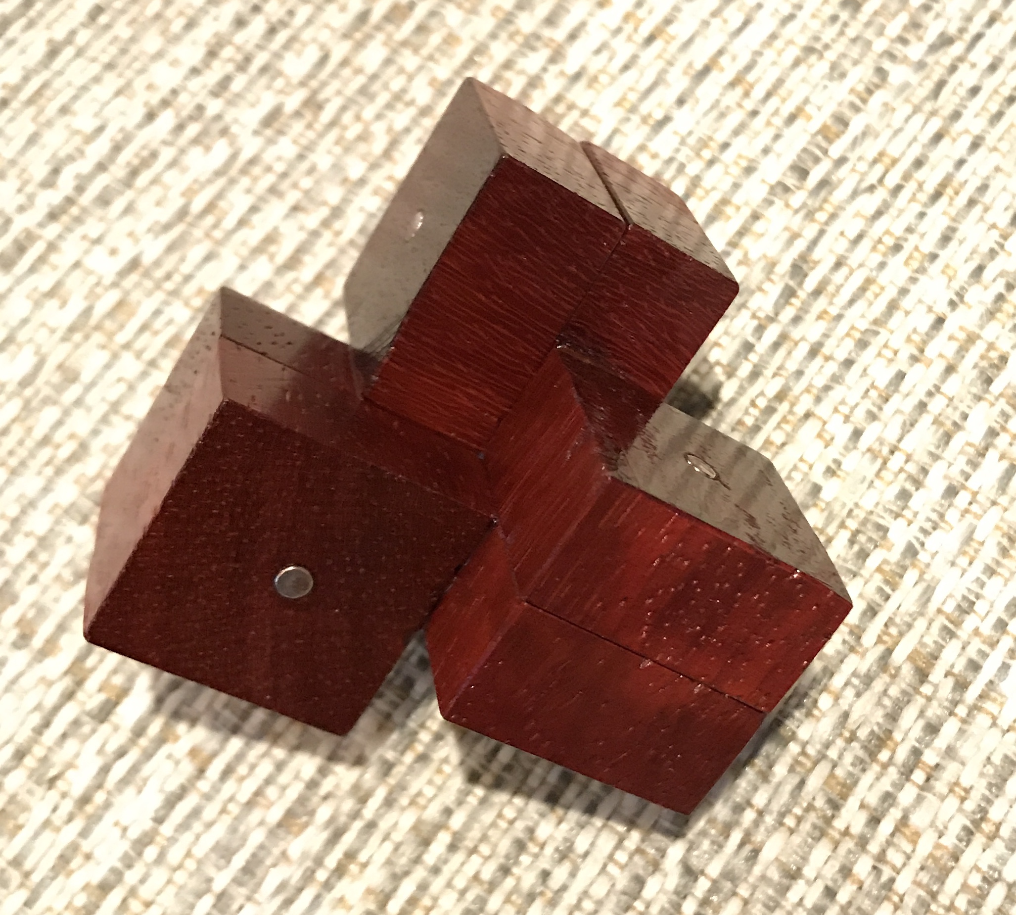
This three piece puzzle was seen on Mr. Puzzle's YouTube channel. A picture of the puzzle as purchased is shown below.
The three pieces are identical conjunctions of two square solids with their widths equal to half their heights. There are two magnets in each piece running through the center of each square. The pieces are symmetrical, simplifying things substantially. The plan is to make each piece from a single piece of wood where each square is 1/2" X 1" X 1". Instead of milling away half of the material from a 1" X 1" X 2" block, I will experiment with cutting two pieces from a slightly larger block. This should be doable with some careful sawing.
One issue yet to be resolved is magnet orientation. In the finished puzzle the aligned magnets need to be attracting. Determining which orientation works will require resolution prior to gluing the magnets in place. Twenty 1/8" X 1/2" rod shaped neodymium magnets were ordered from K & J Magnetics. I may make more than one puzzle!
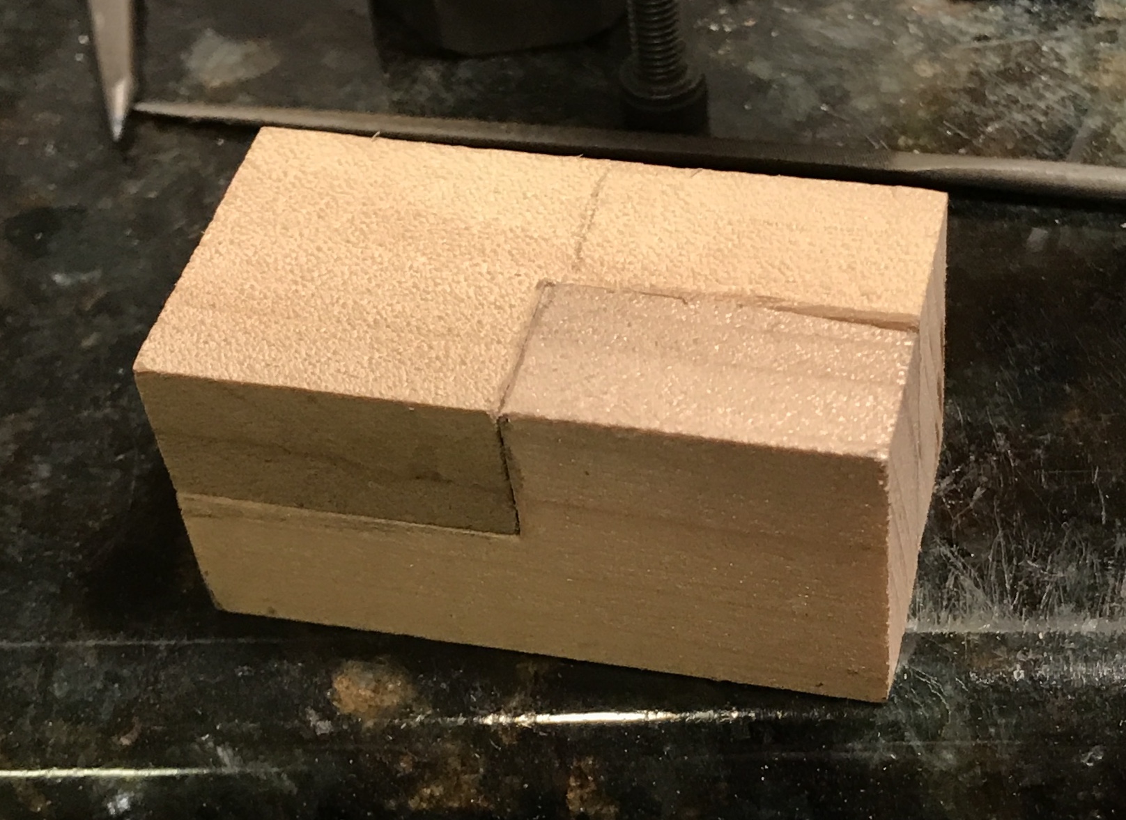
I found a nice block of quartersawn wood that can be used to make 3 pieces without overlapping or 6 with. I do not know the type of wood, but the figuring on it is gorgeous. Before I use this wood I will experiment with some less interesting poplar. Two 3/4" X 3" X 3" blocks of poplar from the joinery class were glued and clamped face-to-face. After letting the glue dry for a few hours the block was cut in half and the two halves were trimmed to 1 1/4" 1 1/4" X 2 1/4" on the table saw. The cut lines were carefully laid out on all 6 faces of the first block. These consist of two through cuts centered on each end oriented at 90° relative to one another and two trickier cuts in the middle to separate the parts. Looking at the left most part in the picture above these trickier cuts are down from the top and in from the right. These cuts are tricky because they are stopped cuts: the cuts must stop half-way through.
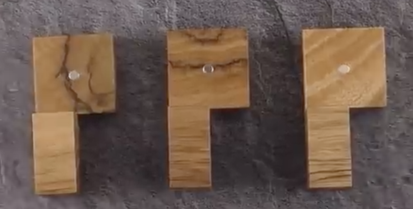
The cuts were made with the Japanese pull saw. The trickier cuts were opened with the back saw and then with some clamping and blocking the cuts were extended all the way into the hidden corners. After separating the parts I realized that this will not work. As can be seen in the picture below the cut needs to be moved farther to the right of center to allow room on the left side for clean-up. Of course that means the cut on the other part will be off the wrong way. In other words there is no way to make this cut and allow wood for clean-up! Time to start milling or routing.
Some work with the router indicated the need for a jig. One was simply constructed from 3/4" Baltic Birch plywood scraps. The back of the jig is about 3" X 5" and has an L-shaped part attached that will serve as the top hold-down for the piece to be cut as well as an end support. The long leg of this L-shaped jig part is 3 1/4" long and 1" wide. The short leg is made from a 1" X 1" scrap and is drilled and tapped through center for a 1/4" X 20 bolt. Two holes were drilled through and countersunk for a #6 X 3/4" wood screw at the end of the long side of the L. Screws were put through these holes and along with glued attached the two arms of the L. The L was similarly attached to the back with two countersunk #6 screws and glue. A 1/2" X 1" X 1" block with a 1/4" hole deeply chamfered was use for the push block.
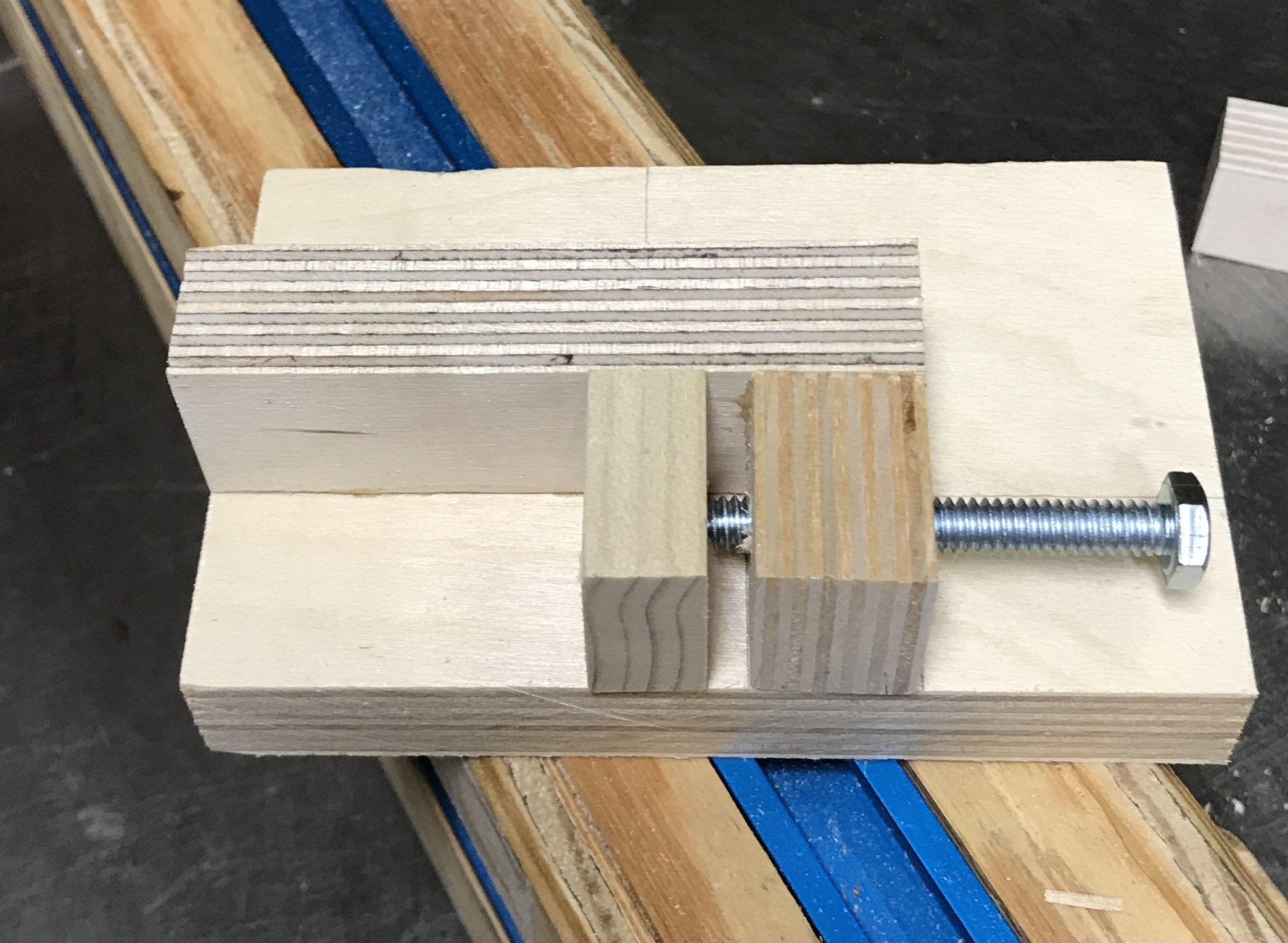
Three 1" X 1" X 2" blocks of poplar were prepared. One was marked for waste removal and placed in the jig. The jig was clamped to the miter gauge. The end of the block was aligned with the 1/2" router bit raised 1/2" above the insert. The screw was screwed in one full turn after marking one edge of the hex head. The block was then clamped to the jig. 0.050" was removed from the end of the block. The block was unclamped, flipped, and the other side was cut. The screw was then moved in two turns (0.100") and the next cut was made on each end. The process was repeated until the remaining wood was about 1/8" thick. The screw was then moved in only one turn and cuts were made on either end. This left only a wafer thin section of wood, which was removed with a knife. Some sanding was done on the block, but sanding the just cut ends only rounds them off. A small 1/2" X 1" block was used as an auxiliary clamping block when more than 1/2" was removed. A second block was cut similarly (about 30 min).
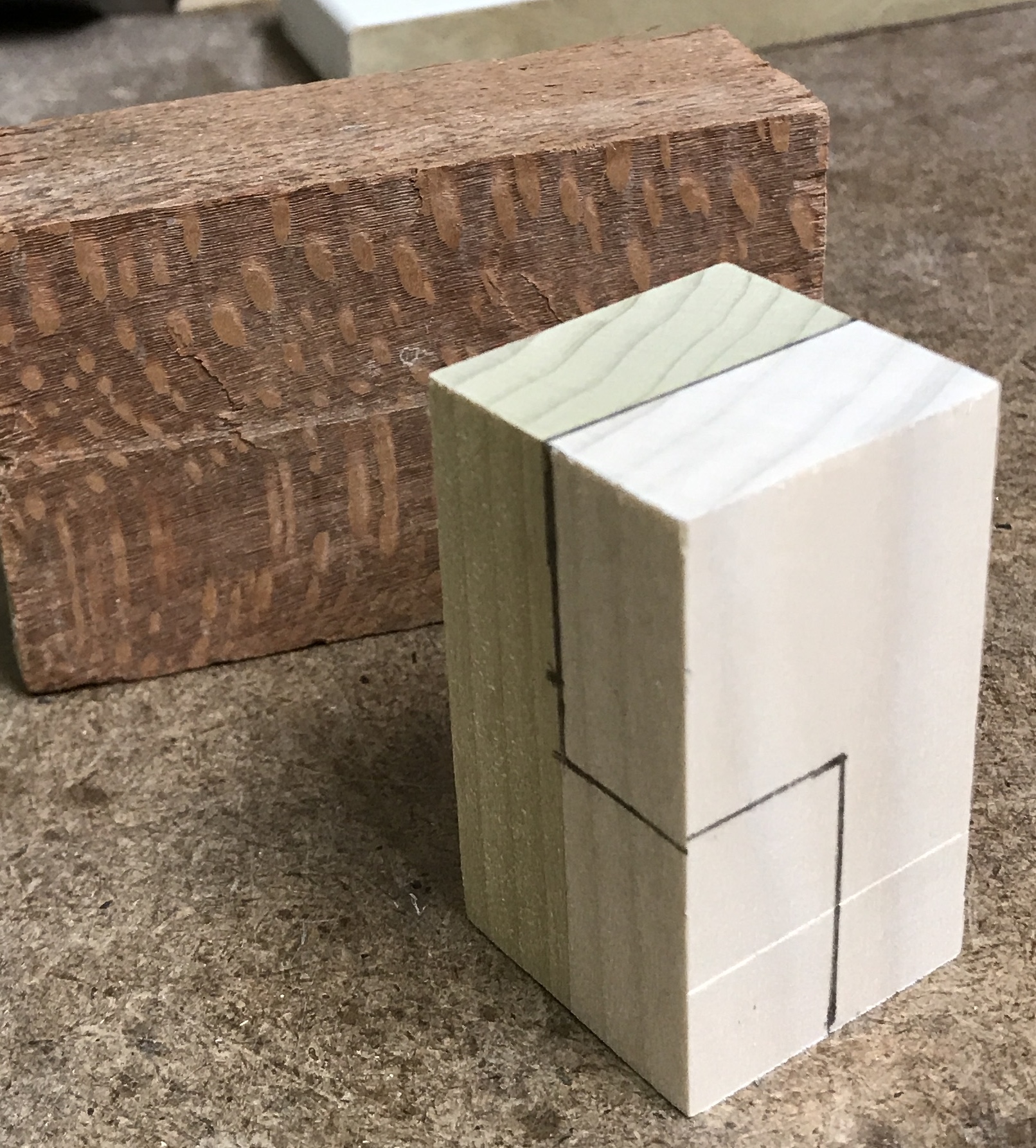
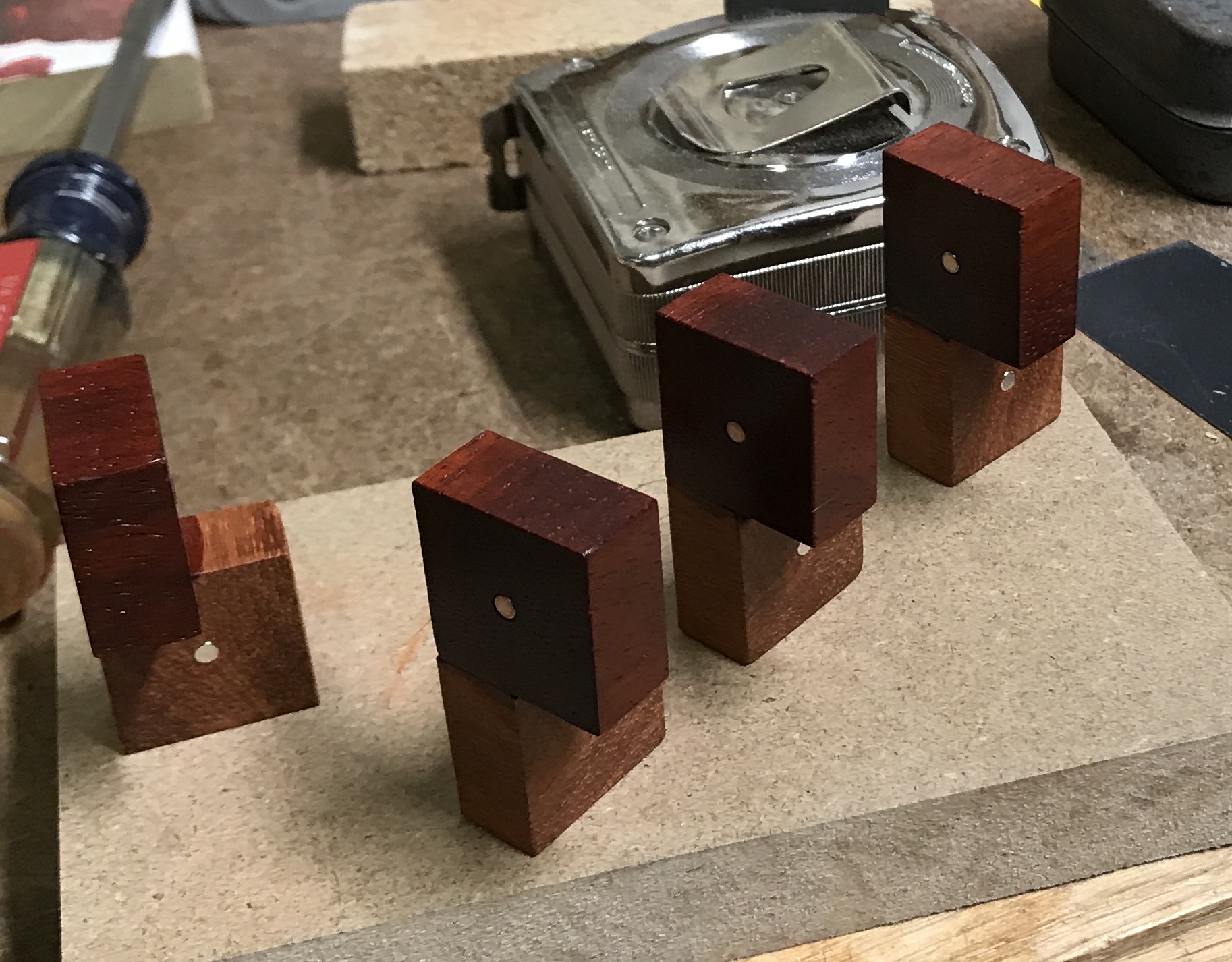
Attempting to put the two blocks together highlighted the need to further trim the small square faces left from routing. As seen in the following picture a small amount needs to be removed so the parts will fit. The rounding from sanding is also visible on the small faces.
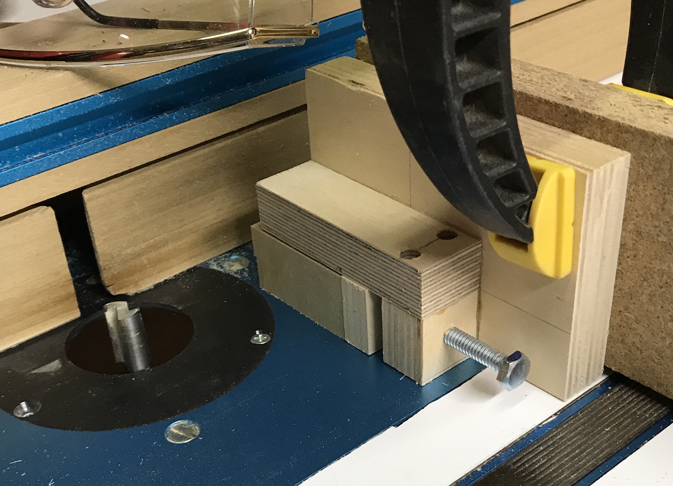
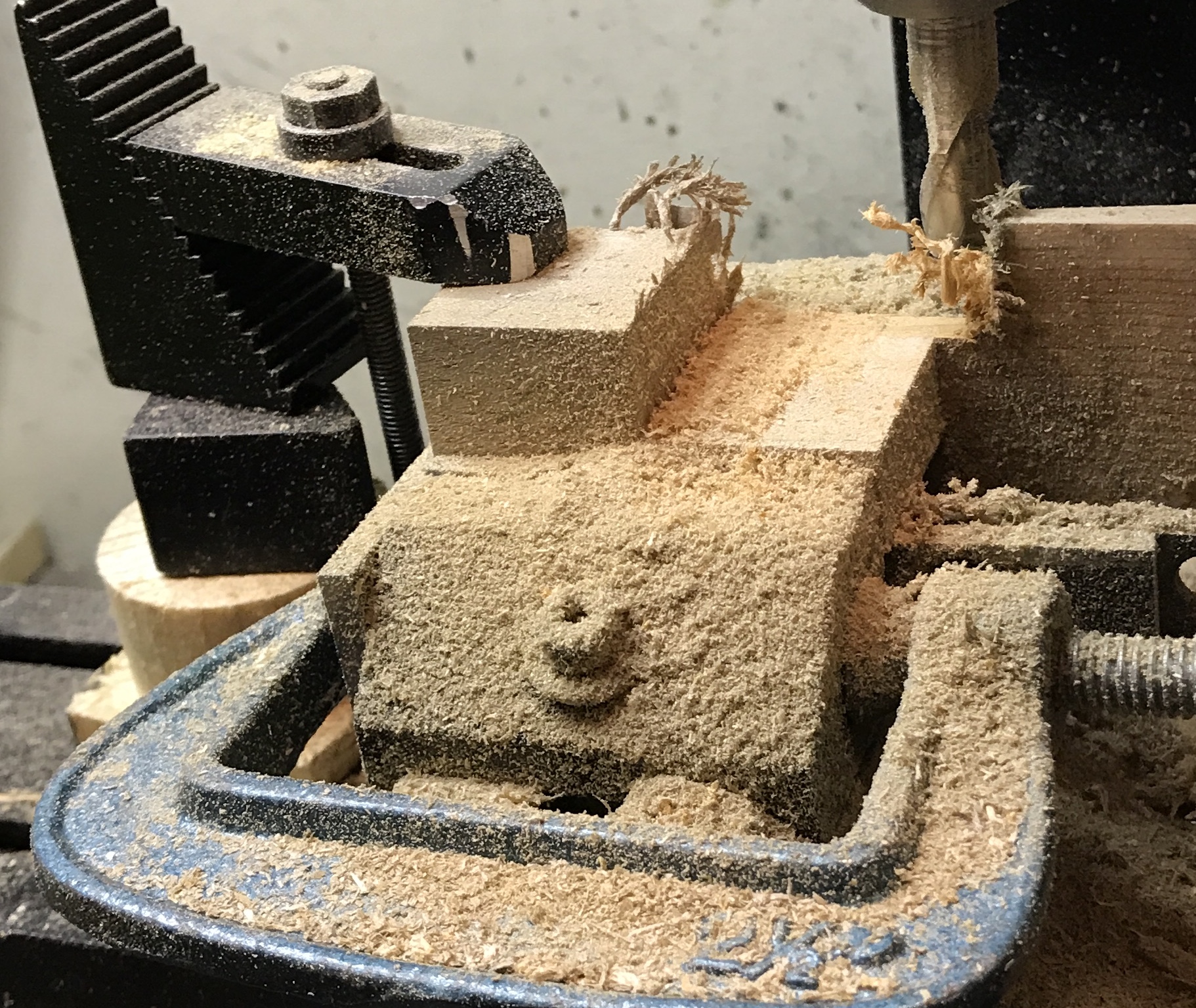
After a slight modification of the jig: a piece of wood was screwed to the end to help minimize tearout there is still some "wobble" from cut to cut. The pieces are just not accurately cut. Maybe the mill is the answer. Potentially, using the vise with parallels to raise the part >1/2", a stop on one side of the vise, and a strap clamp to keep the part from rising out of the vise, I might be able to pull this off with speed and reproducibility. The two remaining poplar blocks are 1.990" X 1.990" X 1.980". A C-clamp was used to hold a parallel across the side of the vise serving as the stop. This along with a strap clamp on top held the block rigidly from three directions. The first pass seemed to work very well. The cuts were made 0.100" across and 0.150" deep. The mill was run at a high speed. The depth was stopped at 0.495" and the width at 0.995". The final measurements will be decided once two parts can be assembled. There was no tearout at the back, but the top had what would be called a burr if this were metal, but in wood might be called "tearup"? This was removed by carefully cutting up the face of the cut and then across the top with a sharp knife.
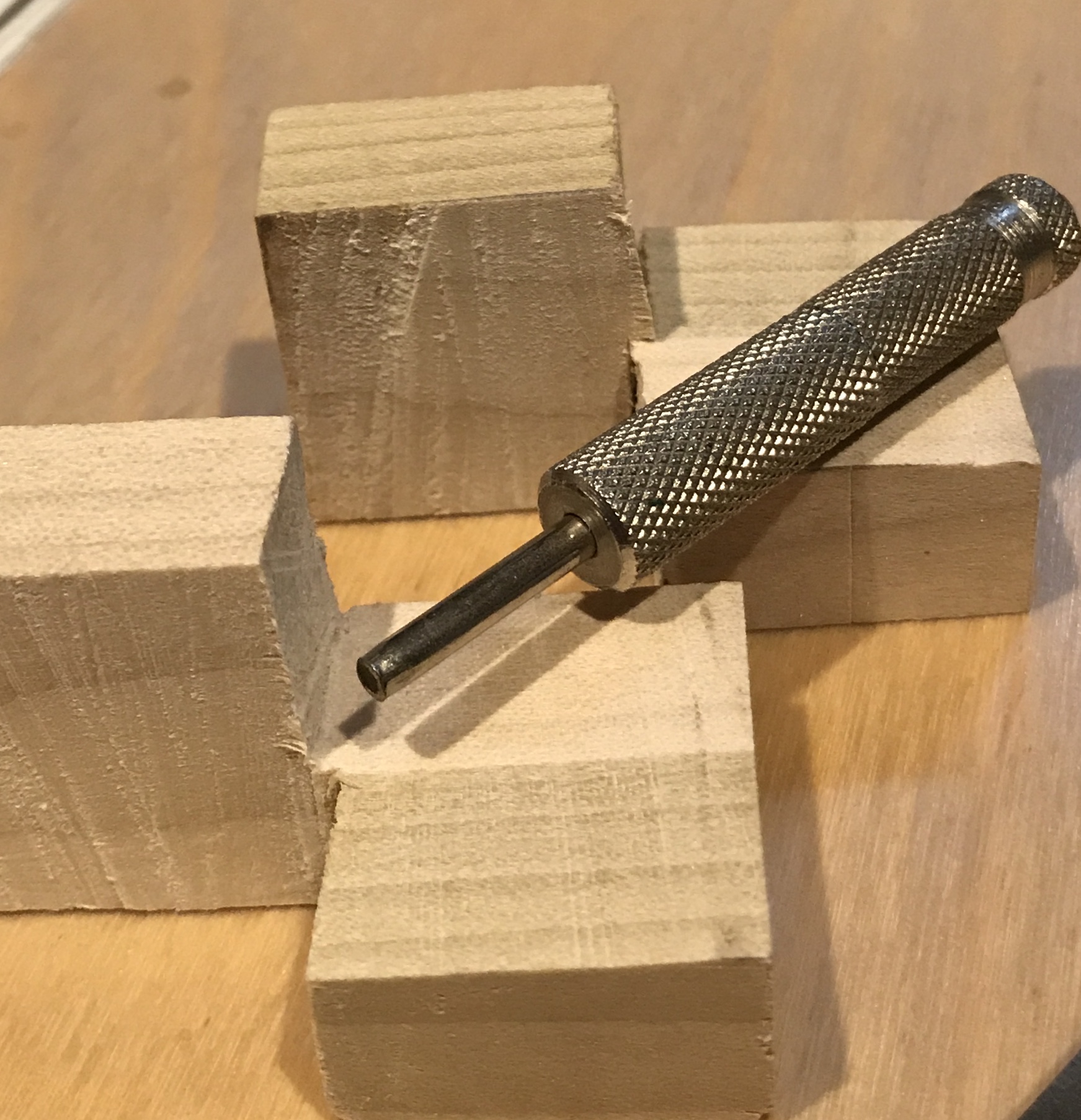
In the picture below you can see the end of the parallel held with the C-clamp that serves as a stop on the left side of the vise. There are two parallels under the wooden part and the backer board continues to the right of the vise. All of the "fur" is also visible on the top edge.
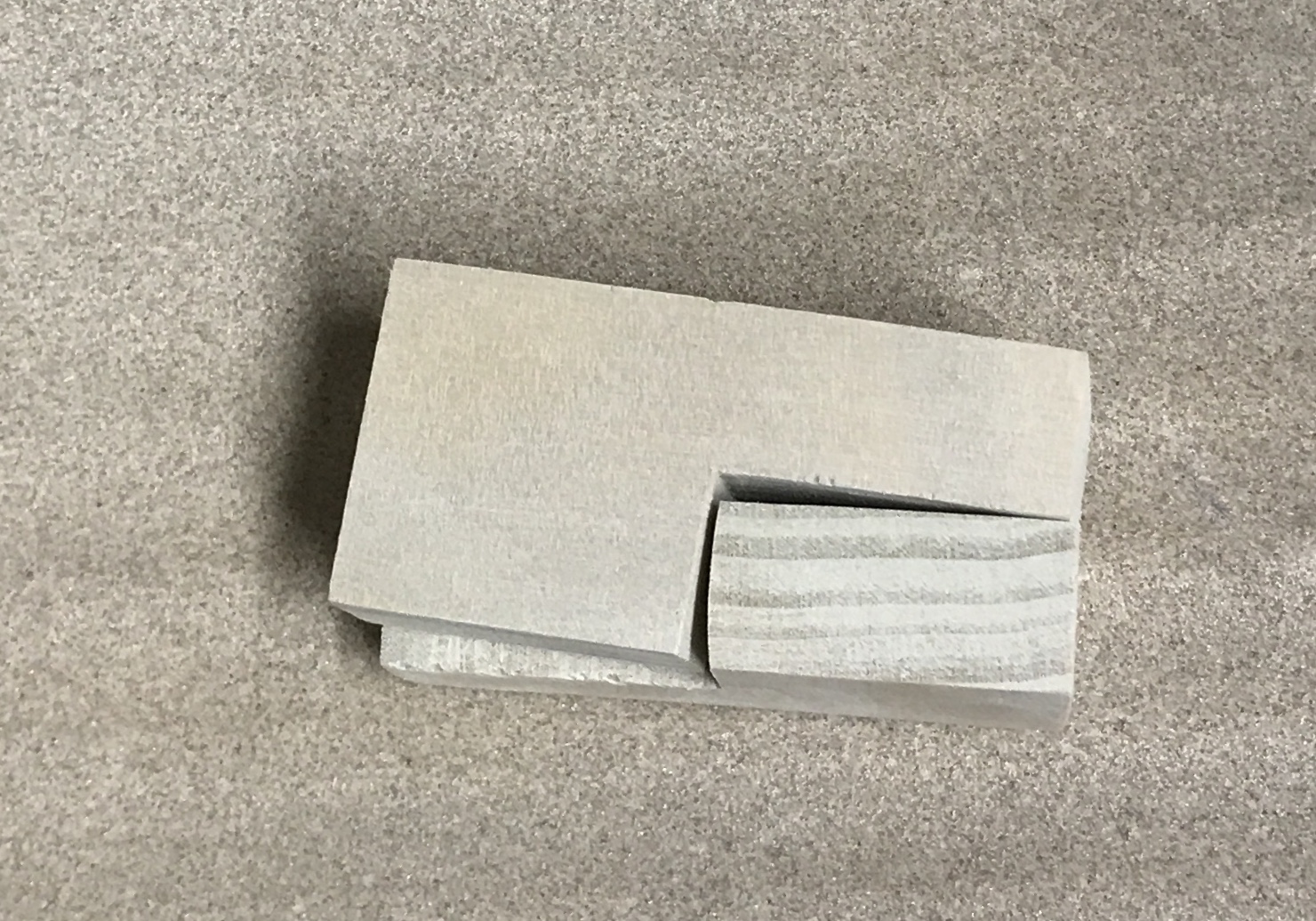
Two poplar parts were made on the mill. The inside corners were gently cleaned with a knife to remove burrs. The image below shows the fit. It is off by < 0.005". Quite nice. Now let's do the same work on three parts made from pretty wood.
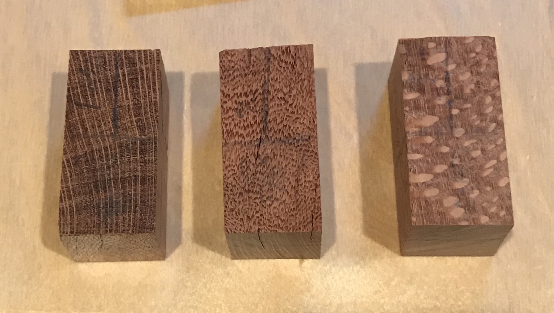
The block of wood chosen was only slightly larger than 2" wide so the dimensions for these puzzle pieces needs to be a bit smaller. The block was only about 3 1/2" long so two pieces were cut with the grain extending from one end of the piece to the other. The third piece has grain across the narrow width.
| Block | Length | Figure W | Grain W |
|---|---|---|---|
| Block 1 | 1.998-2.002 | 0.938-0.945 | 0.907-0.926 |
| Block 2 | 1.970-1.990 | 0.925-0.946 | 0.944-0.944 |
| Block 3 | 1.969-1.985 | 0.946-0.953 | 0.929-0.934 |
As the table above shows there is significant variation and lack of square across the three blocks after cutting on the table saw. Block 2 is the block cut across the grain.
Instead of trying to square up the blocks and cut them all to a common size, the plan is to judiciously make the required cuts to minimize the impact of the non-parallel sides. So, for example, on Block 1 the grain width has a narrow end and this will become the width of a newly cut face. In this way the 1/2" height, the important dimension, will be minimally impacted. Some sanding on the ends and sides of the cut pieces will fix any remaining discrepancies. In general I will aim for piece thickness of 0.465" to 0.475".
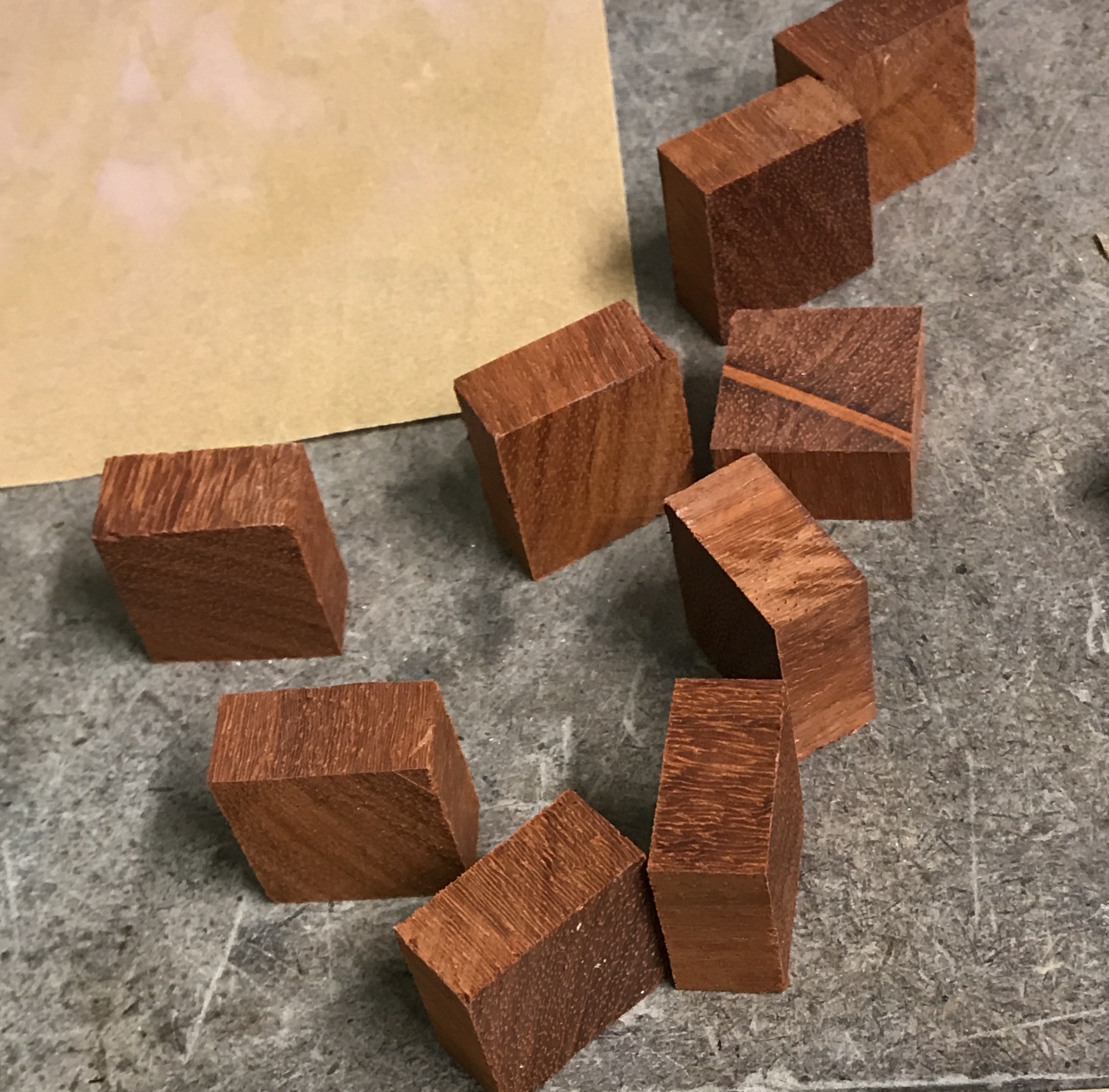
The first two pieces were cut as above. The third was first rough cut with the Japanese saw and then milled to finished size. At one point the wall of the third piece broke off. This was glued and then milling resumed. Had multiple challenges with this piece including tearout in a few places. All three pieces need to have their corners slightly rounded. The lengths of the pieces do not match twice the width so the fit is not ideal. The six widths range from 0.912" to 0.946" with an average of 0.932". To adjust the length each end was to be trimmed about 0.025-0.030". The pieces fit much better now.
The two better pieces were sanded on all sides to 150 grit and the edges were all slightly chamfered with a fine file. This produced about 1/32" of bevel. The third piece needed some repair work. A dab of neutral wood putty was mixed about 1:1 with sanding dust. A drop of glue was added to make the mixture workable. This mix was applied to some of the divots in the third piece and left to dry overnight.
The pieces were drilled for the magnets. Twelve 1/8 X 3/16" cylindrical neodymium magnets were purchased. The holes were drilled on center by width and at 0.49" from the edge. A block of scrap wood was placed beneath the pieces during drilling. They were drilled 0.116" and reamed to 1/8". Since the thickness of each of the pieces was different, steel spacers were made to fit between two magnets. The spacers were made from 1/8" drill rod. This was held in a collet in the lathe, faced, chamfered and parted off at the correct length 0.099", 0.088", & etc. It was difficult to put the spacers in the holes without them going in crooked. While attempting to rescue a crooked spacer one of the pieces broke. This was glued and clamped.
The difficulty of dealing with the odd sizes and differences between pieces made me rethink the process. Taking another look at Mr. Puzzle's video showed that the puzzle pieces were made from two identical square sections. It also clarified the orientation of the magnets: opposite orientations of the two magnets in each piece.
A new block of interesting wood was found that was better sized for the job. A long 1" X 1" blank was cut on the table saw. Seven 1/2" lengths were cut from this blank. These squares were sanded on all faces with 220-grit paper. Unfortunately, they are not square!!
Yet again a block of wood was procured. This one is about 1 1/2" X 1 1/2". One side was cut off to yield a flat surface. This flat surface was placed on the table and both adjacent sides were cut after ensuring the blade was perpendicular to the table. The second cut was set at 1.0". The block was rotated 90° and the last side was cut at 1.0". The sides of this blank were quite square and pretty accurately sized. The miter gauge was squared up and nine 1/2" slices were cut from the blank using a 1/2" spacer against the fence. The blocks produced ranged in width and depth from 0.990" to 1. 10". They were similarly within 0.01" of 0.500" thick except for one block that is 0.532" thick.
The thick block was reduced to 0.50" on the milling machine. Using a ruler for a stop the blocks were clamped in the milling vise on a scrap of wood. The edges were located and the table moved in 0.500" in both directions. The blocks were drilled with a small starter drill, a #32 drill, and a reamed 0.125". They were then sanded on all faces with 220 grit paper and a fine file was used to chamfer all sixteen edges of each of the nine blocks. The best six were selected for use.
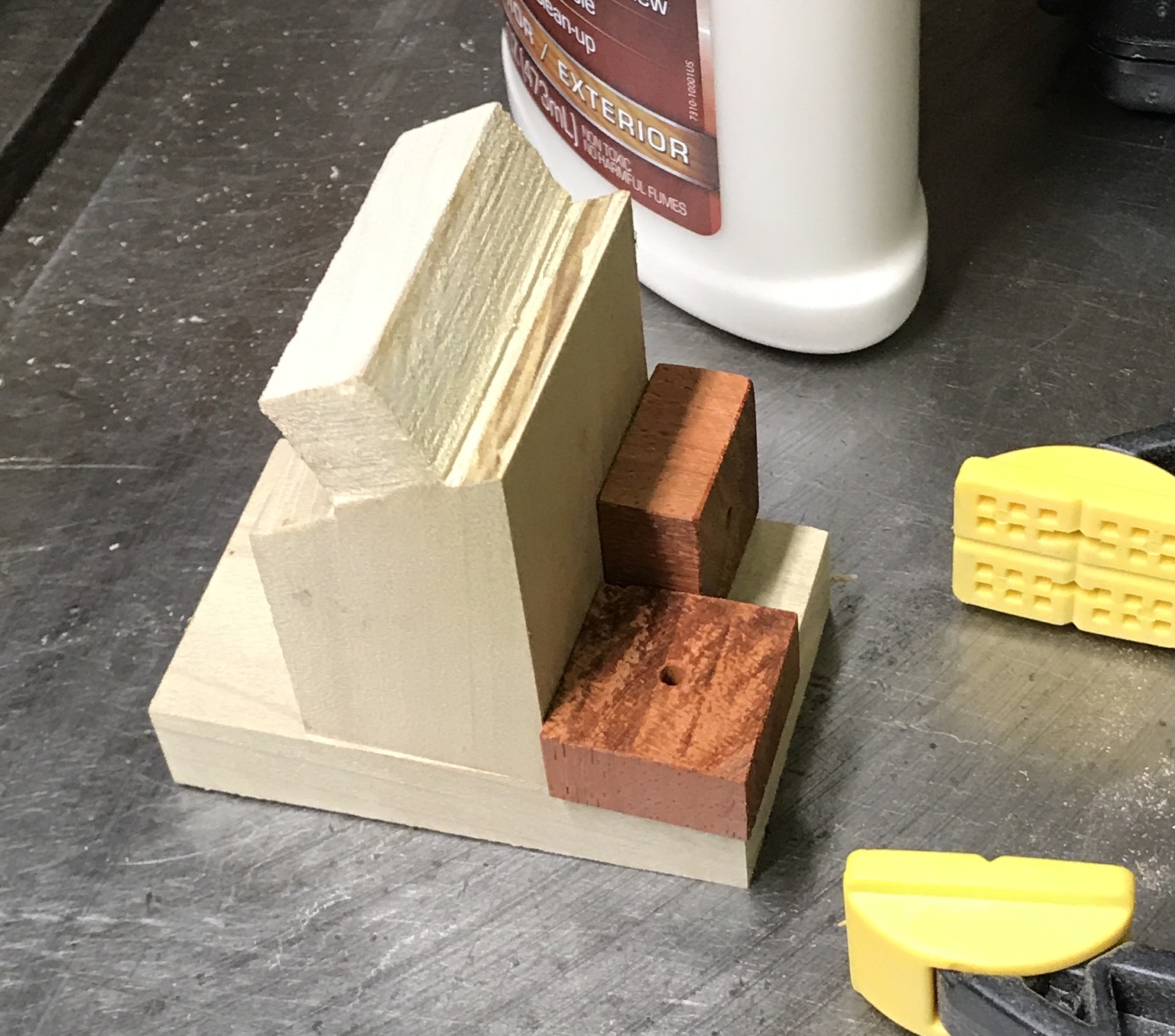
A small clamping jig was made and two of the non-selected blocks were glued and clamped in the jig (photo above). The jig was slightly less than 2" in width so the clamps would seat easily on the blocks. As the glue was drying on this trial piece tung oil finish was explored on a block of the same wood. Both a side and one end of the wood were sanded with 150 grit paper and coated with tung oil. This coat was kept "shiny" for 3 minutes before wiping off the excess. It was then allowed to dry overnight. The tung oil procedure for unstained wood shown below is from Popular Woodworking Vol. 156, pg 79 was used on this test block.
I was not thrilled with the tung oil result. It seemed as though the tung oil had still not filled the pores after three coats. The finish was smooth, but was not the least shiny. Shellac was used on two other faces of the scrap block and gave a nice finish after three coats. The best eight blocks were glued up with the jig as above to make four pieces. These pieces were sanded with 300 grit paper in the areas where squeeze out had occurred. The 1/2" magnets arrived and were inserted using the workbench vise and blocks of wood. A small drop of Loctite was used in each hole. The first coat of shellac was applied to one half of each block as seen in the following picture.
Three coats of shellac later the pieces looked great! Assembly failed! Some of the magnets were not put in correctly. A quick trip to the lathe and a 5/8" long piece of 1/2" hex steel was converted into a small punch with a diameter of 0.120". This and a small wooden cylinder with a hole through it were used to press out one magnet in two pieces. The magnets were turned around, reinserted and pressed into place. No glue was used as the fit was quite tight. The picture below shows the completed and assembled 3-piece puzzle.
Attention!!! Spoiler alert pictured below!